Shaft Diameter 25,4 mm(1 inch)
In case of unfavourable chip formation or poor chip removal, e.g. due to insufficient coolant pressure, the distance WF and/or G must be selected accordingly.
For this purpose, use our stability calculator at https://www.ipz-tooling.de/anwendung/.
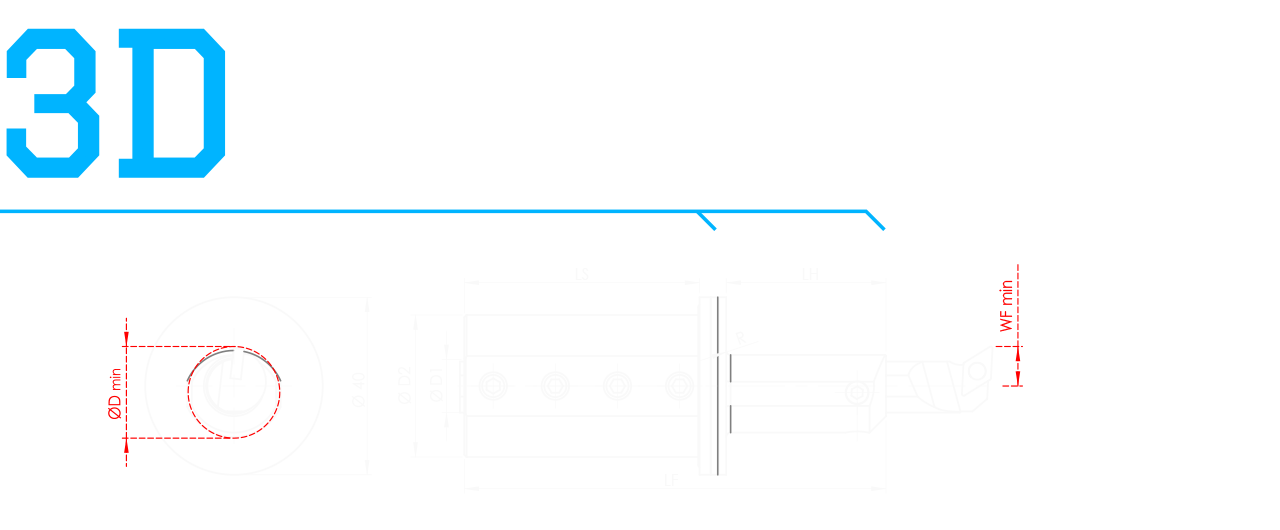
Type | ØD1 | ØD2 | ØD min. | WF min. | LS | LH | LF | Article No. | Spare parts | Illustration |
MINI | 10 | 25,4 | 17,6 | 7 | 53 | 30 | 89 | 10Z01A3-00R/L |  |
Type | ØD1 | ØD2 | ØD min. | WF min. | LS | LH | LF | Article No. | Spare parts | Illustration |
MINI | 12 | 25,4 | 21,5 | 8,5 | 53 | 36 | 95 | 12Z01A3-00R/L |  |
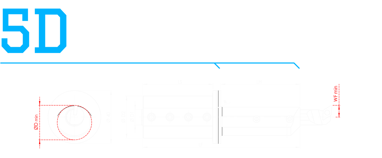
Type | ØD1 | ØD2 | ØD min. | WF min. | LS | LH | LF | Article No. | Spare parts | Illustration |
MINI | 10 | 25,4 | 17,6 | 7 | 53 | 50 | 109 | 10Z01A5-00R/L |  | |
MAXI | 10 | 25,4 | 23,1 | 7 | 53 | 50 | 109 | 10Z01C5-00R/L |  |
Type | ØD1 | ØD2 | ØD min. | WF min. | LS | LH | LF | Article No. | Spare parts | Illustration |
MINI | 12 | 25,4 | 21,5 | 8,5 | 53 | 60 | 119 | 12Z01A5-00R/L |  | |
MAXI | 12 | 25,4 | 29,7 | 9 | 53 | 60 | 119 | 12Z01C5-00R/L |  |

Type | ØD1 | ØD2 | ØD min. | WF min. | LS | LH | LF | Article No. | Spare parts | Illustration |
MINI | 10 | 25,4 | 17,6 | 7 | 53 | 70 | 129 | 10Z01A7-00R/L |  | |
MAXI | 10 | 25,4 | 23,1 | 7 | 53 | 70 | 129 | 10Z01C7-00R/L |  |
Type | ØD1 | ØD2 | ØD min. | WF min. | LS | LH | LF | Article No. | Spare parts | Illustration |
MINI | 12 | 25,4 | 21,5 | 8,5 | 53 | 84 | 143 | 12Z01A7-00R/L |  | |
MAXI | 12 | 25,4 | 29,7 | 9 | 53 | 84 | 143 | 12Z01C7-00R/L |  |